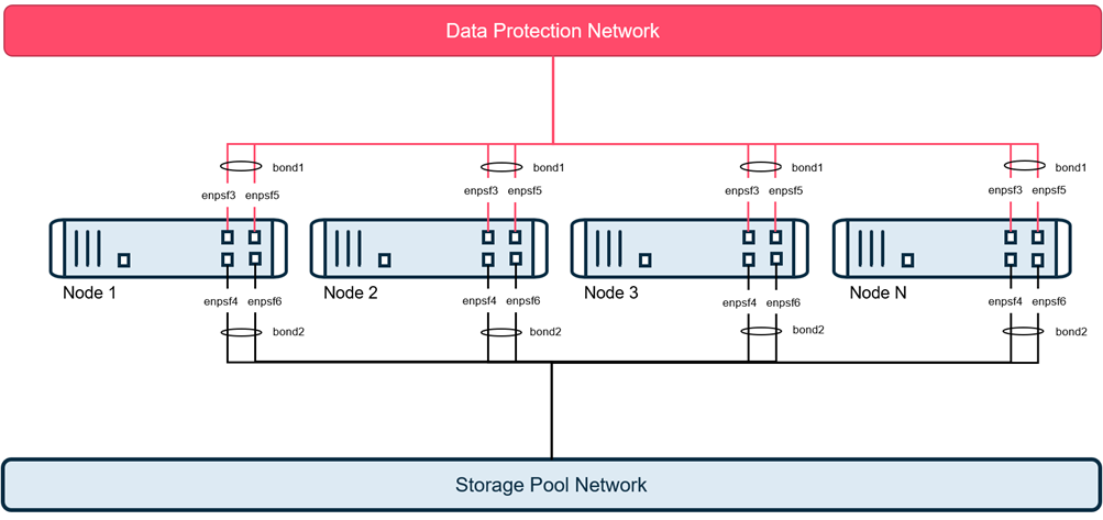
Bonded topology is the most common option for HyperScale as this provides network level redundancy for each node.
In this topology, each node requires connections to 2 separate network as follows:
-
2 - 10 GbE port for data protection network, which transfers data to and from the clients being protected and connect to the CommServe server.
-
2 - 10 GbE port for storage pool network, which is a dedicated private network, used for communication and replication between the HyperScale nodes.
Note
Bonded topology is the most used configuration and is recommended for most deployments. The bonding can be configured to provide redundancy using either the Active-Backup bonding or the Link Aggregation Control Protocol (LACP). This can also be used with a multi-switch link aggregation protocol such as Virtual Port Channel (VPC), MLAG, or MC-LAG to provide switch level redundancy.
-
Each pair will be bonded on the node, so it is treated as one logical connection. If a node encounters a cable, SFP, or network card failures, the node remains operational without any user intervention. This can optionally be setup to connect to 2 switches to provide switch level redundancy.
-
Active-Backup and Link Aggregation Control Protocol (LACP) are the supported bonding modes.
LACP requires the switch(s) to support it as well. When using LACP, each pair of ports should be configured as an active port-channel, and not configured to negotiate the aggregation protocol.
Network Requirements
In this topology, each node requires the following connections:
-
2 - 10 GbE bonded ports for the data protection network, which transfers data to and from the clients. This requires a corresponding IP address for the data protection network.
-
2 - 10 GbE bonded ports for the storage pool which is a dedicated private network, used for communication and replication between the HyperScale nodes. This requires a corresponding IP address for the storage pool network.
Note
Data Protection and storage pool networks MUST be on two separate subnets.
The following network names and IP addresses are required for this topology:
|
Node 1 |
Node 2 |
Node 3 |
Node n |
|
|---|---|---|---|---|
|
Data Protection Fully Qualified Domain Name* |
|
|
|
|
|
Data Protection IP Address* |
|
|
|
|
|
Data Protection Netmask* |
|
|
|
|
|
Data Protection Gateway* |
|
|
|
|
|
Data Protection DNS 1* |
|
|
|
|
|
Data Protection DNS 2 |
|
|
|
|
|
Data Protection DNS 3 |
|
|
|
|
|
Storage Pool IP Address* |
|
|
|
|
|
Storage Pool Netmask* |
|
|
|
|

* Required fields
Note
If you have more than 3 nodes expand the columns in this table to include all the nodes that you plan to setup.
Cabling and Cable Connections
-
Connect 2 - 10 GbE data protection ports from each node to the data protection network.
All data management tasks including backups and restores, are established through these 2 - 10 GbE data protection ports.
-
Connect 2- 10 GbE storage pool port from each node to the private storage pool network.
All storage related tasks, including all cluster connectivity for the storage pool network, will be through these 2- 10 GbE storage pool ports.
-
Connect the 1 GbE IPMI port (BMC Controller) from each node to the IPMI or management or utility network for lights out access.
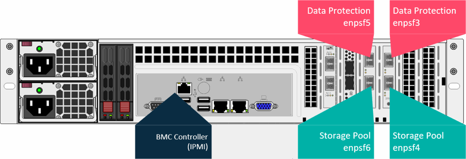
HS4300 Connections
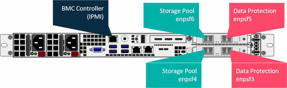
HS2300 Connections
Supported Network Cables
The network interface cards included with the HyperScale nodes support the use of either optical fiber or direct attach copper (Twinax) cabling.
Note
Each node has 2 dual port 10 GbE adapters with an LC SFP+ transceiver installed in each port. These can be used for 10 GbE fiber cabling or, can be removed for copper Twinax cabling if desired. (RJ45 based 10 GbE NICs are available from the factory.)
The following cable connectors are supported:
|
For Optical Fiber Connection |
10GBase-SR SFP+ modules are included for all 4 interfaces on each node to support standard or redundant cabling. You will need to provide 10G Base-SR SFP+ modules for your switch and compatible OM3 or OM4 Multi-mode Fiber Cabling. |
|
|---|---|---|
|
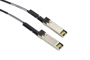
For Direct Attach Copper (Twinax) Connections |
Direct Attach Copper cables are not included with an appliance purchase. When purchasing cables, ensure that they meet the following requirements:
|
|
|
10GBASE-T Support (Copper Twisted Pair) |
10GBASE-T is not supported with the included SFP+ network interface cards. Optional 10GBASE-T network cards are available instead of SFP-based configurations as an option at the time of order placement. Contact your Commvault representative for more information. |
Required Network Cables
You will need several network cables to setup the nodes. Make sure that these cables are available when you setup the nodes.
The following network cables are required per node:
-
1x 1 GbE network cable for the iRMC and management ports
-
4x 10 GbE network cables for the bonded data protection and storage pool ports
To estimate the total number of network cables required to setup all the nodes, multiply the number of nodes in your cluster with the per node requirement.
For example, if you plan to setup 3 nodes in the cluster you will need the following cables:
-
3x 1 GbE network cables for the iRMC ports
-
12x 10 GbE network cables for the bonded data protection and storage pool ports