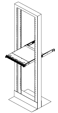
Installing the Rails
This section provides information on installing the ROA 1200 chassis into a rack unit with the rails provided. The following is a basic guideline for installing the system into a rack with the rack mounting hardware provided. You should also refer to the installation instructions that came with the specific rack you are using.
Identifying the Rack Rails
Note
This rail will fit a rack between 26" and 33.5" deep.
The chassis package includes two rack rail assemblies in the rack mounting kit. Each assembly consists of two sections: an inner fixed chassis rail that secures directly to the server chassis and an outer fixed rack rail that secures directly to the rack itself.
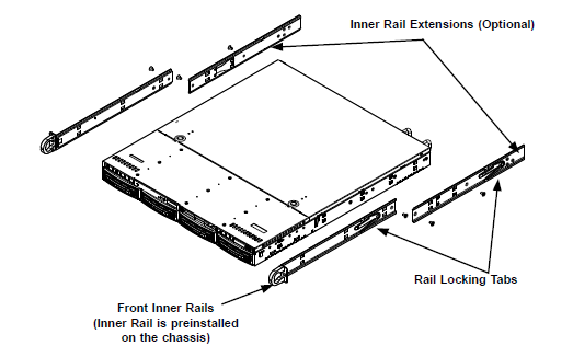
Locking Tabs
Each inner rail has a locking tab. The tabs lock the server into place when installed and pushed fully into the rack. These tabs also lock the server in place when fully extended from the rack. This prevents the server from coming completely out of the rack when you pull it out for servicing.
The Inner Rail Extension (Optional)
The inner rails are pre-attached and do not interfere with normal use of the chassis if you decide not to use a server rack. Attach the inner rail extension to stabilize the chassis within the rack. If you are not using a rack, you do not have to install the inner rail extensions.
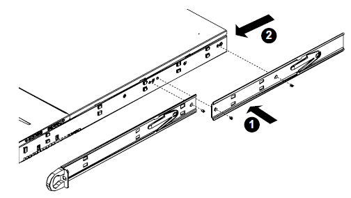
Use the following steps to install the inner rails:
-
Place the inner rack extensions on the side of the chassis aligning the hooks of the chassis with the rail extension holes. Make sure the extension faces outward just like the pre-attached inner rail.
-
Slide the extension toward the front of the chassis.
-
Secure the chassis with two screws as illustrated. Repeat steps for the other inner rail extension.
Warning
Do not pick up the server by the front handles. They are designed to pull the system from a rack only.
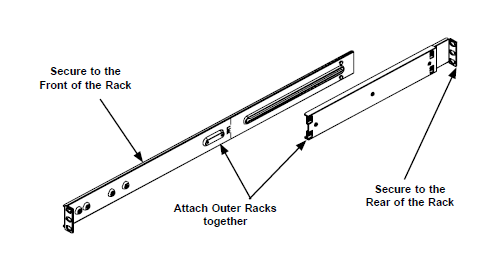
Outer Rack Rails
Outer rails attach to the server rack and hold the server in place. The outer rails for the SC815 chassis extend between 30 inches and 33 inches.
Use the following steps to install the outer rails to the rack:
-
Attach the short bracket to the outside of the long bracket. You must align the pins with the slides. Also, both bracket ends must face the same direction.
-
Adjust both the short and long brackets to the proper distance so that the rail fits snugly into the rack.
-
Secure the long bracket to the front side of the outer rail with two M5 screws and the short bracket to the rear side of the outer rail with three M5 screws.
-
Repeat steps 1-3 for the left outer rail.
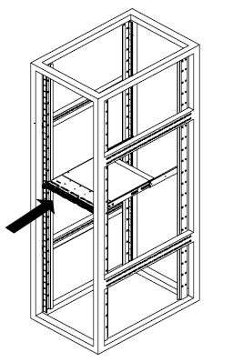
Installing the Chassis into a Rack
Use the following steps to install the chassis into a rack:
-
Confirm that chassis includes the inner rails and rail extensions. Also, confirm that the outer rails are installed on the rack.
-
Line chassis rails with the front of the rack rails.
-
Slide the chassis rails into the rack rails, keeping the pressure even on both sides (it may be necessary to depress the locking tabs when inserting). When the server has been pushed completely into the rack, the locking tabs will click into the locked position.
-
(Optional) Insert and tighten the thumbscrews that hold the front of the server to the rack.
Warning
Stability hazard. The rack stabilizing mechanism must be in place, or the rack must be bolted to the floor before you slide the unit out for servicing. Failure to stabilize the rack can cause the rack to tip over.
Note
The above diagram is for illustrative purposes only. Always install nodes into racks from the bottom up.
Installing the Chassis into a Mid-Mount Position (Telco) Rack
Use the following steps to install the chassis into a mid-mount position in the rack:
-
Use the two L-shaped brackets on either side of the chassis (four total).
-
Determine how far the chassis will extend out the front of the rack. Larger chassis should be positioned to balance the weight between front and back. If a bezel is included on your server, remove it.
-
Attach the two front brackets to each side of the chassis, then the two rear brackets positioned with just enough space to accommodate the width of the telco rack.
-
Finish by sliding the chassis into the rack and tightening the brackets to the rack.
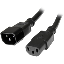
Cabling the Power Supplies
Each appliance has redundant power supplies which can be connected to two independent power sources.
The supplied cables will fit the power receptacles in a typical enclosure. Alternate power cables may be needed if the enclosure does not support C13 connections. Each node should be connected to two power sources.
Use the following steps to connect the appliance to the power supply:
-
Connect the first power supply unit (PSU) of each node to the first power source in the enclosure rack.
-
Connect the second PSU of each node to the second power source in the enclosure rack.
The power cables provided with each node are compatible with 110 VAC or 250 VAC.
Cabling the RO1200 Appliance
The Remote Office Appliance requires a minimum of two connections
-
1 gigabit Ethernet connection for IPMI out of band management.
-
1 gigabit or 10 gigabit connection for management and data protection traffic.
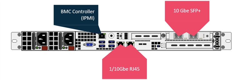
The Remote Office Appliance 1200 has two connectivity options for management and data protection traffic, leveraging RJ45 or SFP+ ports.
-
For RJ45 connections, standard UTP Category 6a cabling can be used for distances up to 100 meters (330ft). For shorter distances under 55 meters (180 ft) category 6 cabling can be used.
-
For SFP+ Connections both SFP+ Optical Transceivers and Direct Attach Copper (DAC) cabling are supported.
For Optical Fiber Connection
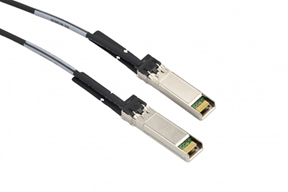
For Direct Attach Copper (Twinax) Connections
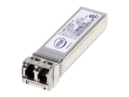
10 G Base-SR SFP+ modules are included for both interfaces on the appliance to support standard or redundant cabling.
You will need to provide 10 G Base-SR SFP+ modules for your switch and compatible OM3 or OM4 Multimode Fiber cabling.
Direct Attach Copper cables are not included with an appliance purchase. When purchasing cables, ensure that they meet the following requirements:
-
Any SFP+ passive or active limiting direct attach copper cable, that complies with the SFF-8431 v4.1 and SFF-8472 v10.4 specifications.
-
Maximum cable length for passive cables is 7 meters.
-