You can configure cascading network gateway connections using advance network settings.
The network gateways are configured between CommCell entities, such as the CommServe computer and client displayed in the following diagram:
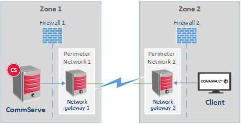
Use this procedure to configure incoming and outgoing connections on the four CommCell entities that are shown in the diagram: CommServe computer, Network gateway 1, Network gateway 2, and Client.
Note
Although the diagram and procedure describe a CommServe computer and a client, the two CommCell entities can be any combination of CommServe computer, MediaAgent, and client.
Before You Begin
The Commvault network gateway computers must be configured.
Procedure
Step 1: Configure the CommServe host
Configure the rules for the CommServe computer to block incoming connections from Network gateway 1, and then force outgoing connections through the VPN tunnel to Network gateway 2 through Network gateway 1, and to the client through Network gateway 1.
-
Log on to the CommServe host, using an account with administrator rights.
-
Expand Client Computers, then right-click the CommServe> Properties, and then click Network.
-
On the Network Route Configuration tab, select Configure Network Route Settings.
-
Block incoming connections from Network gateway 1:
-
On the Incoming Connections tab, click Add.
-
Click the From list, then select the client name of your Network gateway 1 server.
-
Click the State list, then select BLOCKED.
-
Click OK.
-
-
Force outgoing connections to Network gateway 2 that come through Network gateway 1 into the tunnel:
-
Click the Outgoing Routes tab, then click Add.
-
Click the Remote Group/Client list, then select the client name of your Network gateway 2 server.
-
Under Route Type, select Via Network Gateway. Note that Force all data (along with control) traffic into the tunnel is automatically selected also.
-
In the Network Gateway Settings area, click the Remote Network Gateway list, then select the client name for your Network gateway 1 server.
-
Click OK.
-
-
Force outgoing connections to the client that come through Network gateway 1 into the tunnel:
-
Click Add.
-
Click the Remote Group/Client list, then select the client name.
-
Under Route Type, select Via Network Gateway. Note that Force all data (along with control) traffic into the tunnel is automatically selected also.
-
Click the Network Gateway Settings > Remote Network Gateway list, then select the client name for your Network gateway 1 server.
-
Click OK.
-
Step 2: Configure Network gateway 1
Configure the network rules for Network gateway 1 to restrict incoming connections from both the CommServe computer and Network gateway 2, and then force the outgoing connection to the client through Network gateway 2 through the VPN tunnel.
-
Under Client Computers, right-click Network gateway 1 > Properties, and then click Network.
-
On the Network Route Configuration tab, select Configure Network Route Settings.
-
Select Advanced, then click OK.
-
Restrict incoming connections from the CommServe host:
-
On the Incoming Connections tab, click Add.
-
Click the From list, then select the client name of your CommServe host.
-
Click the State list, then select RESTRICTED.
-
Click OK.
-
-
Restrict incoming connections from Network gateway 2:
-
Click Add.
-
Click the From list, then select the client name of your Network gateway 2 server.
-
Click the State list, then select RESTRICTED.
-
Click OK.
-
-
Force outgoing connections to the client through Network gateway 2, into the tunnel:
-
Click the Outgoing Connections tab, then click Add.
-
Click the Remote Group/Client list, then select your client name.
-
Under Route Type, select Via Network Gateway. Note that Force all data (along with control) traffic into the tunnel is automatically selected also.
-
Click the Network Gateway Settings > Remote Network Gateway list, then select the client name of your Network gateway 2 server.
-
Click OK.
-
Step 3: Configure Network gateway 2
Configure the network rules for Network gateway 2 to restrict incoming connections from Network gateway 1 and the client, and then force the outgoing connection to the CommServe computer through Network gateway 1.
-
Under Client Computers, right-click Networkgateway2 > Properties, and then click Network.
-
On the Network Route Configuration tab, select Configure Network Route Settings.
-
Select Advanced, then click OK.
-
Restrict incoming connections from Network gateway 1:
-
On the Incoming Connections tab, click Add.
-
Click the From list, then select the client name of your Network gateway 1 server.
-
Click the State list, then select BLOCKED.
-
Click OK.
-
-
Restrict incoming connections from the client:
-
Click Add.
-
Click the From list, then select the name of your client.
-
Click the State list, then select RESTRICTED.
-
Click OK.
-
-
Force outgoing connections to the CommServe host through Network gateway 1, into the tunnel:
-
Click the Outgoing Connections tab, then click Add.
-
Click the Remote Group/Client list, then select your CommServe client.
-
Under Route Type, select Via Network Gateway. Note that Force all data (along with control) traffic into the tunnel is automatically selected also.
-
Under Network Gateway Settings, click the Remote Network Gateway list, then select the client name for your Network gateway 1 server.
-
Click OK.
-
Step 4: Configure the client
Configure the client’s network rules to block incoming connections from Network gateway 2, and then force outgoing connections through the VPN tunnel to Network gateway 1 through Network gateway 2, and to the CommServe computer through Network gateway 2.
-
Under Client Computers, right-click the client > Properties, and then click Network.
-
On the Network Route Configuration tab, select Configure Network Route Settings.
-
Block incoming connections from Network gateway 2:
-
On the Incoming Connections tab, click Add.
-
Click the From list, then select the client name of your Network gateway 2 server.
-
Click the State list, then select BLOCKED.
-
Click OK.
-
-
Force outgoing connections to Network gateway 1 through Network gateway 2, into the tunnel:
-
Click the Outgoing Connections tab, then click Add.
-
Click the Remote Group/Client list, then select the client name of your Network gateway 1 server.
-
Under Route Type, select Via Network Gateway. Note that Force all data (along with control) traffic into the tunnel is automatically selected also.
-
Under Network Gateway Settings, click the Remote Network Gateway list, then select the client name for your Network gateway 2 server.
-
Click OK.
-
-
Force outgoing connections to the CommServe host through Network gateway 2, into the tunnel:
-
Click Add.
-
Click the Remote Group/Client list, then select the client name of your CommServe host.
-
Under Route Type, select Via Network Gateway. Note that Force all data (along with control) traffic into the tunnel is automatically selected also.
-
Under Network Gateway Settings, click the Remote Network Gateway list, then select the client name for your Network gateway 2 server.
-
Click OK.
-
Step 5: Push the network configurations
Push the network configurations in the following order:
-
Client
-
Network gateway 2
-
Network gateway 1
-
CommServe computer
To push the network configuration, right-click the CommCell entity from the CommCell Browser, and then click All Tasks > Push Network Configuration.