HyperScale X Appliance nodes can be deployed with bonded data protection and storage pool interfaces, using the Mode 1 Active-Backup bonding used for redundancy or fault tolerance.
To setup the mode 4 (802.3ad) bonding used for load balancing and fault tolerance, see Deploying the nodes with LACP bonding.
This Simple Configuration method allows you to setup all the nodes in the storage pool together. If you would like to setup the nodes individually, use the Advanced Configuration.
Before You Begin
Verify the requirements needed for setting up the Bonded Topology in your environment.
Tip
Keep the network names and IP addresses listed in the Network Requirements section of Bonded Topology handy before you start the configuration. This will help you to accurately add the details during the deployment.
Procedure
-
Log on to one of the nodes using the system console as described in Setting up a Static IP For IPMI. (Do not use PuTTy / SSH to setup the nodes.)
-
Launch the network configuration interface using the following command:
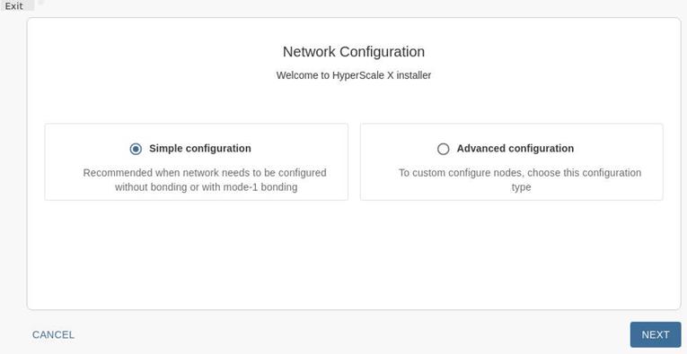
# hsxsetupThe Network Configuration page appears.
-
Click Simple configuration and then click NEXT.
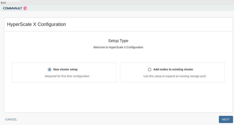
The Setup Type page appears.
-
Click New cluster setup and then click NEXT.
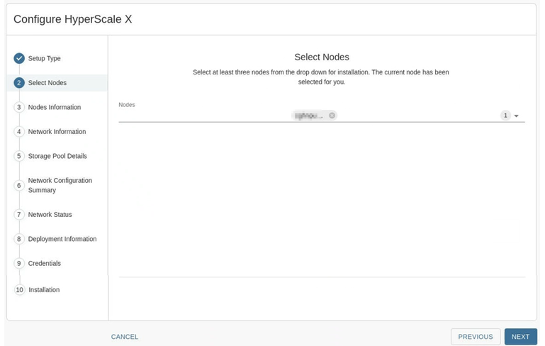
The Select Nodes page appears.
-
Select the nodes as follows:
-
Click the down arrow
 at the top right area of the page to view a list of available nodes.
 -
Click and select the nodes that must be included in the storage pool.
Note
You can select up to 12 nodes at a time for the initial deployment. Nodes are listed by serial number. If one or more nodes are missing from the list, there is likely a cabling or network configuration issue. To troubleshoot, see Troubleshooting Network Configuration Errors.
-
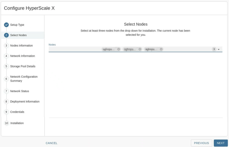
Click NEXT.
The selected nodes will be listed in the Select Nodes page.
Once completed your screen should be similar to the one shown in the following image: (The number of nodes will vary depending on the number of nodes you select.)
-
Click NEXT.
The Nodes Information page appears.
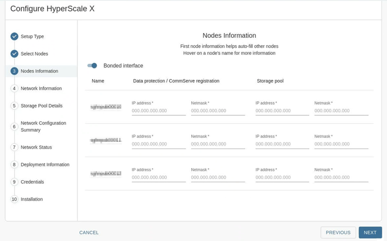
-
-
Add the following information:
-
The Bonded interface toggle key is enabled, by default, for active-backup bonding. (No additional action needed.)
Note
Bonding requires a minimum of 4x 10 GbE interfaces connected to each node. If any of the nodes do not have sufficient connections or if one or more connections are down, the toggle key will be disabled. Exit the installer, configure the network and then restart the installer.
-
Under Data protection/CommServe registration, enter the IP address and Netmask associated with the first node.
Note
Sequential IP addresses and matching subnet masks for data protection is automatically populated for the other nodes. If the nodes have non-sequential IP addresses, manually fill-in the respective data protection IP addresses for the nodes.
-
Under Storage pool, enter the IP address and Netmask associated with the first node.
Note
Sequential IP addresses and matching subnet masks for storage pool is automatically populated for the other nodes. If the nodes have non-sequential IP addresses, manually fill-in the respective storage pool IP addresses for the nodes.
-
Verify and validate the IP address and Netmask associated with the other nodes using the checklist available in Basic Topology. If necessary, edit the information to make sure that the correct network related information is provided.
Tip
Hover the cursor over the node name to view the port related information in each node.
-
Click NEXT.
The Network Configuration page appears.

-
-
Add the following information:
-
In the Default Gateway box, add the IP address associated with the default gateway.
-
In the DNS Servers box, add the IP address associated with the DNS Server.
Click ADD to add additional DNS servers. A maximum of 3 DNS servers can be added.
Note
Multiple DNS servers are recommended.
-
Click NEXT.
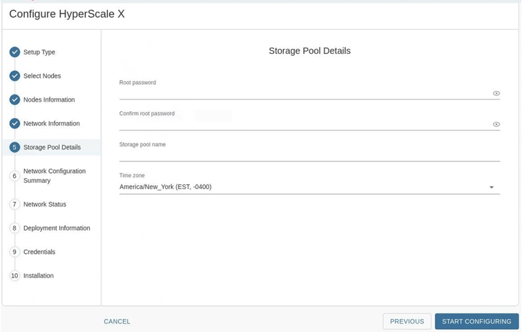
The Storage Pool Details page appears.
-
-
Add the following information:
-
In the Root password and Confirm password boxes, type a secure password for the nodes.
Tip
Hover the cursor over the Root password box to view the password requirements.
-
In the Storage pool name box, type a name for the storage pool associated with the cluster.
The storage pool name can include numbers and alphabets. Special characters cannot be used in the storage pool name.
Tip
Note down the storage pool name. This will be helpful to identify the storage pool in the Command Center.
-
From the Time zone list, select the time zone in which the nodes are located.
-
Click START CONFIGURING.
Note
The setup process configures the network for the nodes. This will take some time to complete.
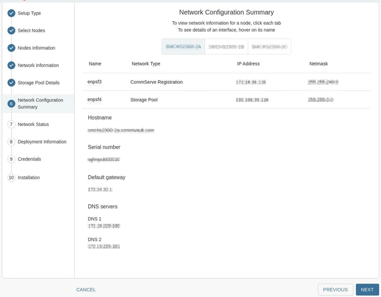
The Network Configuration Summary page appears once the network is configured in the nodes.
-
-
Verify the network configuration by clicking the tab associated with each node. Ensure that the nodes are accurately configured and then click NEXT.
Verify the following information.
-
IP address and Netmask for the data protection interface is accurate.
-
IP address and Netmask for the storage pool interface is accurate.
-
Hostname and serial number associated with the node is accurate.
Note
If you need to change the Hostname do so now. To change the hostname modify and correct the DNS records, (forward and reverse records) as discussed in Setting Up the DNS.
-
Default gateway and DNS servers are accurately configured.
Note
If an error is found, or if the hostname was changed, click PREVIOUS to go back and correct the values in the Node Information page.
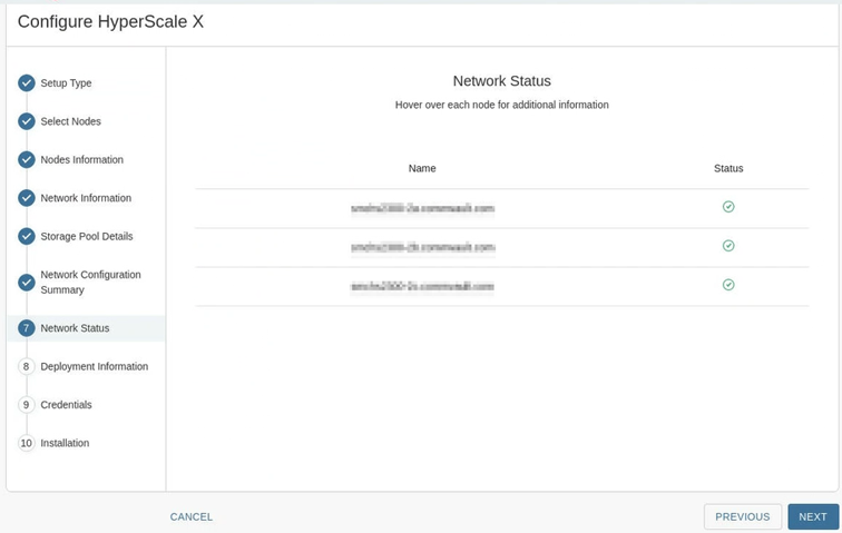
The Network Status page appears.
-
-
Check the status to ensure that all the nodes are reachable. (All the nodes should have a green status.) Click NEXT.
Note
If an error is found, hover your cursor over the status icon to view more information on the error.
The Deployment Information page appears
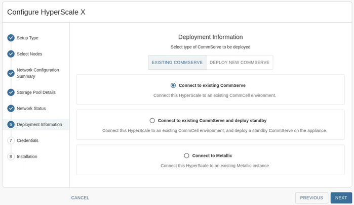
-
Continue the configuration depending on your CommServe server deployment.