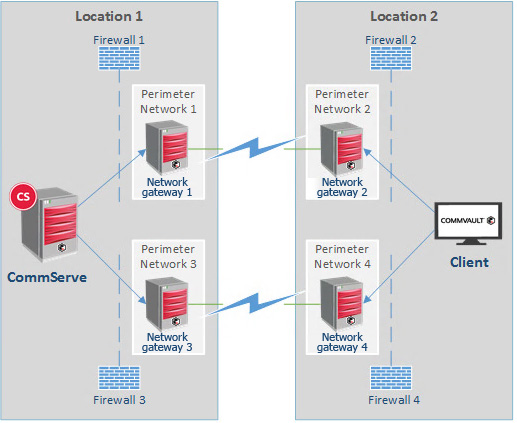
You can define multiple dual-network gateway paths between two CommCell entities. The dual-network gateway paths can be set as alternate routes so that the two CommCell entities can connect to each other. The following diagram provides a representation of this configuration:

Use this procedure to configure incoming and outgoing connections on the six CommCell entities that are shown in the diagram: CommServe computer, Network gateway 1 through Network gateway 4, and Client.
Note
Although the diagram and procedure depict a CommServe computer and a client, the two CommCell entities can be any combination of CommServe computer, MediaAgent, and client.
Before You Begin
The Commvault network gateway computers must be configured.
Procedure
-
Step 1: Create four server groups
Create four server groups as follows:
-
Create a server group named Clients, and then add all of the clients to the group.
-
Create a server group named CS/MA, and then add the CommServe and internal MediaAgents to the group.
-
Create a server group named Internal Network Gateways, and then add the internal network gateways (for example, Network Gateway 1 and Network Gateway 3 in the diagram above) to the group.
-
Create a server group named External Network Gateways, and then add the external network gateways (for example, Network Gateway 2 and Network Gateway 4 in the diagram above) to the group.
-
-
Step 2: Create the first network topology
Create the first network topology as follows:
-
From the Command Center navigation pane, go to Administration > Network > Network Topologies.
-
From the Network topologies pane, click Add topology.
The Add topology dialog box is displayed.
-
In the Name field, enter a name for this topology.
-
For Client type, select Servers.
-
From the Topology type list, select Network Gateway.
-
Select the server groups as follows:
-
For Trusted Server group 1, select CS/MA.
-
For Trusted Server group 2, select External Proxies.
-
For Network gateway or DMZ group, select Internal Proxies.
-
-
Click Save.
-
-
Step 3: Create the second network topology
Create the second network topology as follows:
-
From the Command Center navigation pane, go to Administration > Network > Network Topologies.
-
From the Network topologies pane, click Add topology.
The Add topology dialog box is displayed.
-
In the Name field, enter a name for this topology.
-
For Client type, select Servers.
-
From the Topology type list, select Via proxy.
-
Select the server groups as follows:
-
For Trusted Server group 1, select Clients.
-
For Trusted Server group 2, select Internal Proxies.
-
For Proxy/DMZ group, select External Proxies.
-
-
Click Save.
-
-
Step 4: Create the third network topology
Create the third network topology as follows:
-
From the Command Center navigation pane, go to Administration > Network > Network Topologies.
-
From the Network topologies pane, click Add topology.
The Add topology dialog box is displayed.
-
In the Name field, enter a name for this topology.
-
For Client type, select Servers.
-
From the Topology type list, select Via proxy.
-
Select the server groups as follows:
-
For Trusted Server group 1, select Clients.
-
For Trusted Server group 2, select CS/MA.
-
For Proxy/DMZ group, select External Proxies.
-
-
Click Save.
-
-
Step 5: Create the fourth network topology
Create the fourth network topology as follows:
-
From the Command Center navigation pane, go to Administration > Network > Network Topologies.
-
From the Network topologies pane, click Add topology.
The Add topology dialog box is displayed.
-
In the Name field, enter a name for this topology.
-
For Client type, select Servers.
-
From the Topology type list, select Via proxy.
-
Select the server groups as follows:
-
For Trusted Server group 1, select CS/MA.
-
For Trusted Server group 2, select Clients.
-
For Proxy/DMZ group, select Internal Proxies.
-
-
Click Save.
-
-
Step 6: Push network configurations
Push the network configurations for each network topology you just created, as follows:
-
From the Command Center navigation pane, go to Administration > Network > Network Topologies.
-
From the Network topologies pane, click the Actions button for a topology you just created, and then click Push network configuration.
-
Repeat Step 2 for each network topology you just created.
-