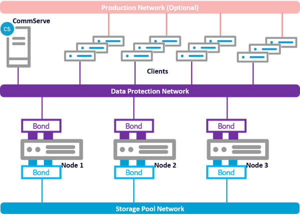
The HyperScale 1.5 Appliance can be setup with bonded interfaces using 4 10GigE ports per node as follows:
-
2 bonded ports for Data Protection
-
2 bonded ports for internal Storage Pool
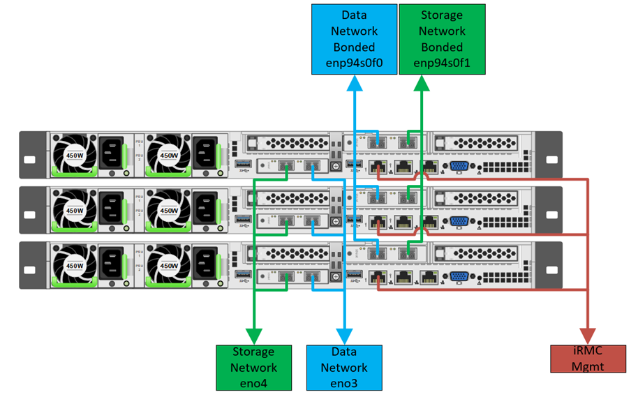
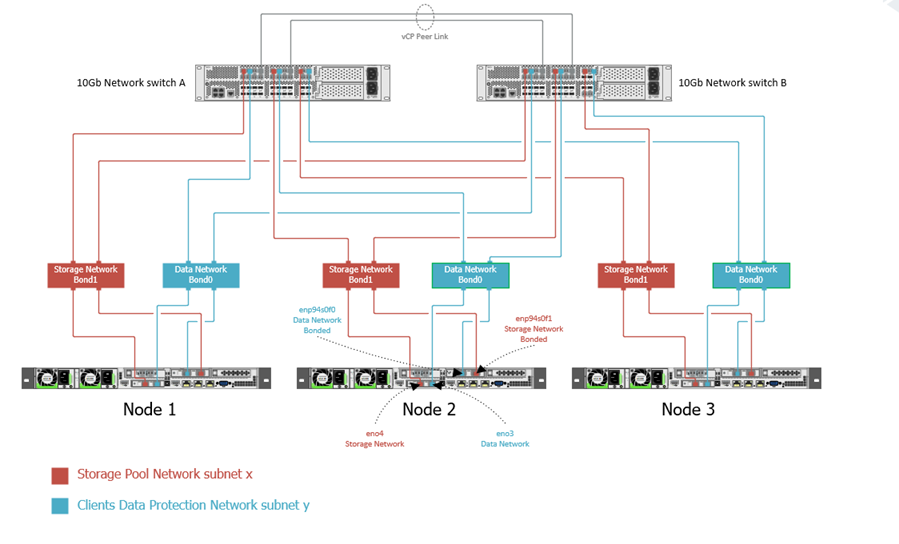
Refer to the following diagrams for cabling a bonded connection:
HS3300 bonded connection diagram
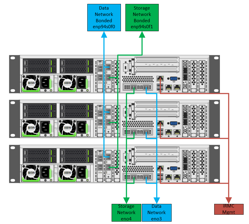
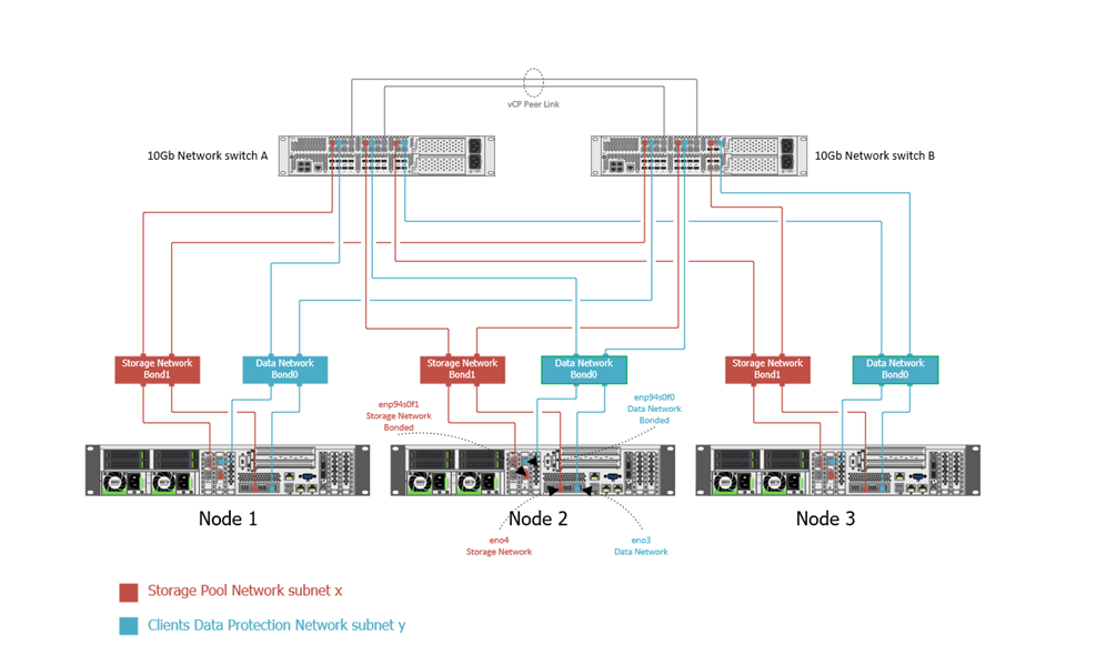
HS1300 bonded connection diagram
This setup requires 2 IP addresses per node.
Ports can be bonded using either mode1 (redundancy or failover) or mode 4 (performance or link aggregation)
Optional Production Network for clients can be used to segregate production traffic from the backup traffic. When this network is not available, all production and backup traffic traverses the same network.
Note: The Commvault HyperScale wizard uses DHCP to automatically detect and setup the nodes and the CommServe.
Before You Begin
-
Use the data collected in the Pre-Installation Checklist to setup the nodes.
-
Using
pingor any other DNS command / tool, ensure that the DNS entries are available for the CommServe, Control Host and each of the MediaAgent nodes.Ensure that both the forward and reverse lookups are available for these entities.
-
Power on the nodes.
The node will automatically boot to Red Hat Enterprise Linux Server.
Important
Power on 3 nodes at a time.
-
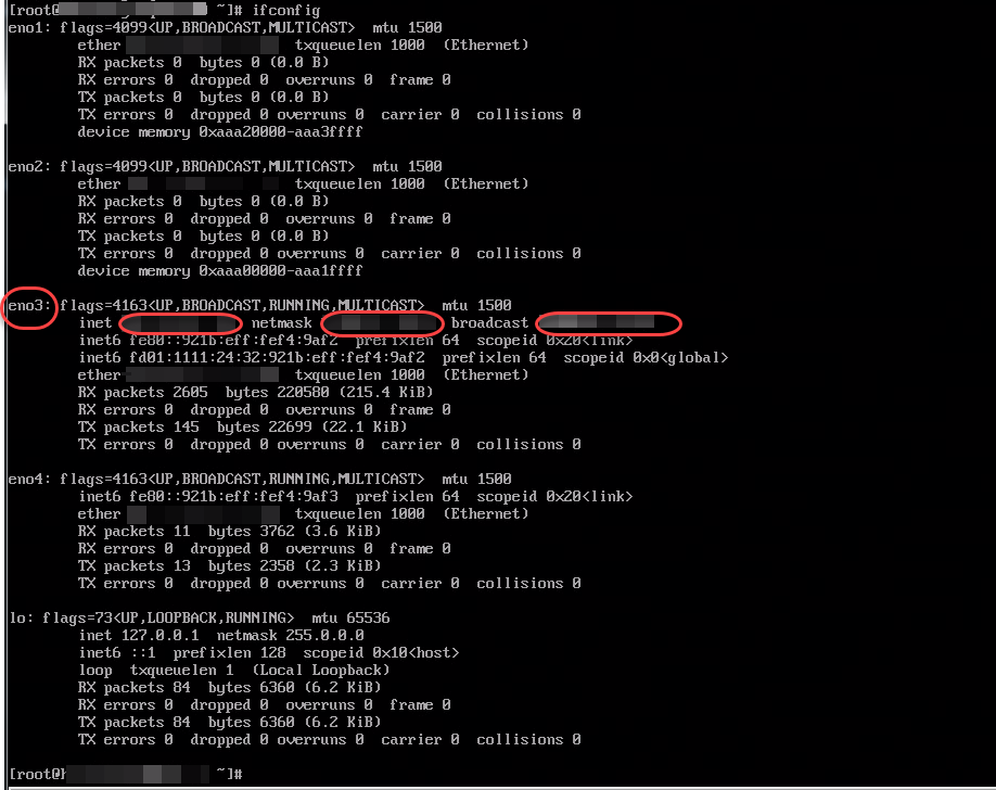
Run the
ifconfigcommand from each node and note down the IP address and the corresponding network interfaces.Click here to view a sample output of the command.
-
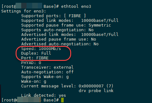
Run the
ethtoolon each of the specific interfaces to verify that they correspond to the 10 GB network interface.Click here to view a sample output of the command.
-
Make sure that the firewall ports are enabled between the data protection and iRMC management networks. Mainly the nodes should be able to communicate with the iRMC ports. The setup will fail if there is a communication failure between these ports. For information about ports required by iRMC, see Firewall Port Requirements.
-
If you plan to attach the nodes to an existing CommServe, make sure that you are logged in as an user with necessary permissions on the CommServe to install the software. For more information about the permissions needed to setup the node as a client in the CommServe, see User Security Permissions by Feature - Deployment. (If necessary, the deployment permission can be removed for the user after the installation, as this permission check is performed only when the nodes are registered in the CommServe.)
Procedure
-
Open a Web browser from any computer that can connect to the nodes.
-
Type the IP address associated with any one of the nodes.
The Commvault HyperScale wizard is displayed.
-
Type root as the Username and cvadmin as the Password.
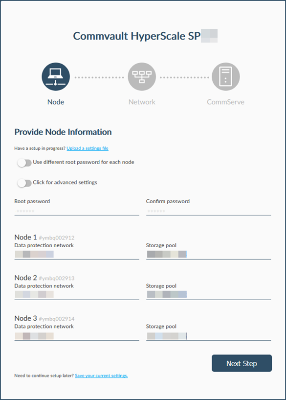
The Provide Node Information page is displayed.
-
Add the Root password / Confirm password for the node(s).
Optional: Click the Use different root password for each node toggle key to setup unique passwords for each node.
-
Click and enable the Advanced Settings toggle key.
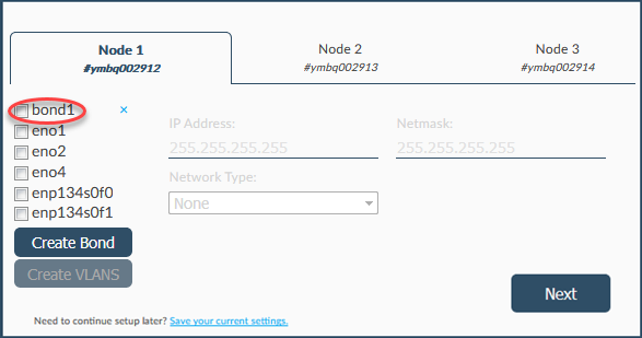
The Node 1, Node 2 and Node 3 tabs will be displayed. The serial numbers associated with each node is also displayed.
All the network interfaces in the hardware is displayed. (Typically, for the standard hardware, a total of 6 interfaces, which includes 4 - 10 GigE interfaces, and 2 - 1 GigE interfaces, are displayed for each node.)
Tip
Hover the cursor over the check box associated with the interface to display the network capacity and other information associated with the interface.
-
Create a bonded interface for Data Protection as follows:
-
Select and enable the check box associated with 2 - 10 GigE interface cards that will make up the network bond. (For example, eno1 and enp94s0f0.)
Tip
Hover the cursor over the check box associated with the interface. Use the Mac Address to identify the interfaces associated with a NIC.
-
Click the Create button.
The bonded interface is listed on the right, similar to the following image:
-
Select and enable the check box associated with the newly added bond.
-
'The Bond mode pop-up will be displayed.
-
From the Bond mode list, select 1 or 4.
Mode
Name
Description
1
Active-backup policy
Interfaces are bonded for redundancy (or fault tolerance mode). Only one interface works at a moment and the other one will work when the first one fails.
4
Link Aggregation Control Protocol (LACP) (802.3ad)
Interfaces are bonded for performance (or dynamic link aggregation mode) by creating aggregation groups which have the same speed. It needs a switch which supports IEEE 802.3ad dynamic link.
-
-
Repeat the above step to create the bonded interfaces for Data Protection and Storage Pool networks.
-
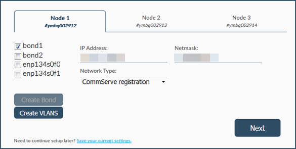
Set the Data Protection interface using the following steps:
-
Select the check box associated with the bonded 10 GigE interface. (For example, bond1.)
-
Verify and validate the IP Address and Netmask addresses using the data collected in the Pre-Installation Checklist.
If necessary, edit the information to make sure that the IP addresses are provided.
-
From the Network Type list, select CommServe registration.
Once completed your screen should be similar to the following image:
-
-
Clear the check box associated with the Data Protection interface.
-
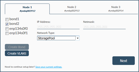
Set the Storage Pool interface using the following steps:
-
Select the check box associated with the bonded 10 GigE interface. (For example, bond2.)
-
Verify and validate the IP Address and Netmask addresses using the data collected in the Pre-Installation Checklist.
If necessary, edit the information to make sure that the IP addresses are provided.
-
From the Network Type list, select StoragePool.
Once completed your screen should be similar to the following image:
-
-
Clear the check box associated with the Storage Pool interface.
-
Repeat the process of defining the interfaces (starting from step 6 to step 11) on the other nodes.
-
Click Next.
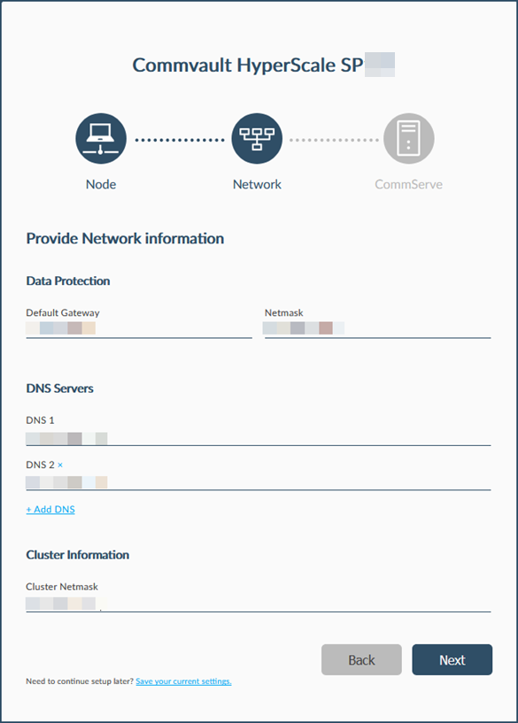
The Provide Network Information page is displayed.
-
The IP addresses associated with the Default Gateway, Netmask, DNS Servers, and Cluster Netmask is displayed.
Verify and validate the information using the data collected in the Pre-Installation Checklist.
If necessary, edit the information to make sure that the correct network related information is provided.
Note
DNS 1 and DNS 2 are mandatory. The setup will fail if only one DNS Server is available. If you have additional DNS Servers, click the Add DNS link to add additional DNS servers.
-
Click Next.
This process may take some time to complete.
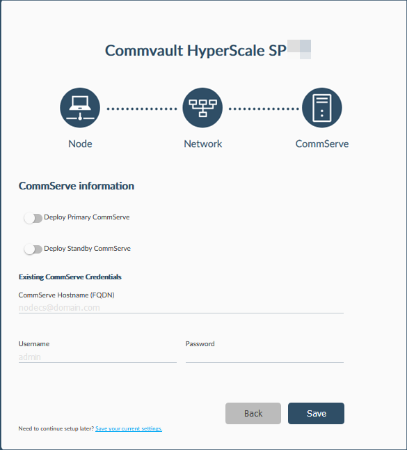
The CommServe Information page is displayed.
-
Choose one of the following CommServe setup options:
Attach the nodes to an Existing CommServe (Default)
Note
If the CommServe is located behind a firewall, you must perform additional steps to connect to the CommServe. For more information, see Connecting To a CommServe Behind a Firewall During Setup.
-
In the CommServe Host Name (FQDN) box, enter a fully qualified domain name for the CommServe computer.
-
In the Username box, enter the user name that must be used to access the CommServe server.
-
In the Password box, enter the password associated with Username.
Setup a Primary CommServe in the nodes
-
Enable the Deploy Primary CommServe option.
The CommServe Information page will display the following options:
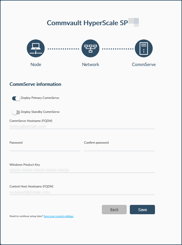
-
In the CommServe HostName (FQDN) box, enter a fully qualified host name for the primary CommServe computer.
-
In the Password / Confirm Password boxes, enter a password for the CommServe server.
Note
This is the 'Admin' password which must be used later to login to the CommServe computer and to access the Command Center and the Control Host.
-
In the Windows Product Key box, enter the Windows product key provided in the package.
Note
Make sure to accurately type the Windows Product Key. If the key is typed with incorrect number of characters, the interface will be stuck. To overcome the issue, refresh the web browser and re-start the installation.
-
In the Control Host Hostname (FQDN) box, enter a fully qualified host name for the control node.
Setup a Standby Disaster Recovery (DR) CommServe in the nodes
-
Enable the Deploy Standby CommServe option.
The CommServe Information page will display the following options:
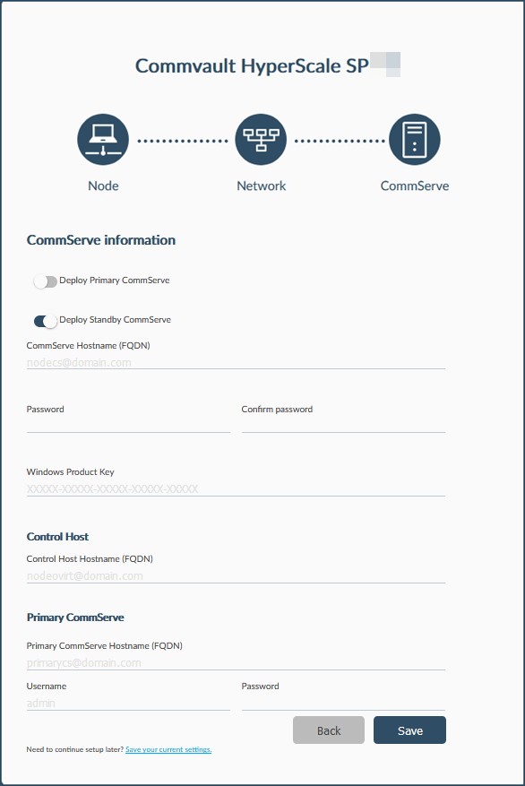
-
In the CommServe HostName (FQDN) box, enter a fully qualified host name for the standby CommServe computer.
-
In the Password / Confirm Password boxes, enter a password for the standby CommServe server.
-
In the Windows Product Key box, enter the Windows product key provided in the package.
Note
Make sure to accurately type the Windows Product Key. If the key is typed with incorrect number of characters, the interface will be stuck. To overcome the issue, refresh the web browser and re-start the installation.
-
In the Control Host Hostname (FQDN) box, enter a fully qualified host name for the control node.
-
In the Primary CommServe HostName (FQDN) box, enter a fully qualified host name associated with the primary CommServe computer.
-
In the Username box, enter the user name that must be used to access the CommServe server.
-
In the Password box, enter the password associated with Username.
-
-
Click Save.
The software will start the installation process.
If you are setting up a Primary or standby CommServe, a virtual machine is setup as the CommServe host. This process may take some time (approximately 45 minutes) to complete.
You can monitor the progress using the progress bar.
Caution
Do not reboot or stop the installation during this process.
Tip
In the course of the installation, the IP address used in the Web browser to access the Commvault HyperScale wizard will switch to the static IP address associated with one of the nodes. If you have to restart the setup, use the FQDN associated with that node to re-launch the wizard in the Web browser.
This completes the setup.
What to Do Next
-
Launch the Command Center as described in Opening the Command Center.
-
Launch the Virtualization Manager and set the value of Total Virtual CPUs to 16 for the HE (Hosted Engine) VM. For more information, see HE Migration Error.
-
If you have attached the nodes to an existing CommServe, make sure that you have the necessary permissions to configure and manage the HyperScale Storage pools. For more information about HyperScale permissions , see User Security Permissions by Feature - HyperScale.
Additional Notes
-
Snapshots or VSA backups of HyperScale Appliance hosted Commserve VM within RHV is not supported. Do not setup snapshot or VSA backups of the Commserve VM as this can render the Commserve unrecoverable. Setup Disaster Recovery backups and/or CommServe LiveSync operation to protect and recover the CommServe.
-
When you setup the standby DR (Disaster Recovery) CommServe host on the nodes, the nodes must be setup as a new storage pool . The nodes cannot be added as additional nodes to an existing Storage Pool. For more information on configuring a new HyperScale storage pool, see Configuring a Scale-Out Storage Pool.