Use this procedure to deploy Commvault Grid nodes using a bonded network topology.
In this topology:
- Two interfaces are bonded for CommServe registration and data protection traffic.
- Two interfaces are bonded for storage pool communication.
- Network redundancy is provided through either Active-Backup bonding or Link Aggregation Control Protocol (LACP).
Bonded Topology is the recommended deployment model for most production environments because it provides network resiliency and protects against individual cable, NIC, or switch failures.
Supported Bonding Modes
Active-Backup (Mode 1)
Active-Backup bonding provides fault tolerance by keeping one interface active while the second interface remains on standby. If the active interface fails, traffic automatically switches to the standby interface.
Link Aggregation Control Protocol (LACP) (Mode 4)
LACP combines multiple interfaces into a logical connection and requires switch support. Each bonded interface pair must be configured as an active port-channel on the switch infrastructure.
Note
-
During the setup process, ensure that the following passwords do not contain the special characters
',",/,~, or\:- Root password
- Restricted shell user (
cvbackupadmin) password - CommServe connection password
-
When deployment is complete:
- Password-based root access is disabled.
- Firewall protection is enabled.
- Ransomware protection is enabled automatically.
Before You Begin
-
Select the resiliency mode relevant to your environment. For guidance, see Selecting Resiliencey.
-
If you plan to connect to an existing CommServe server, gather the following information before you begin:
-
The fully qualified domain name (FQDN) of the CommServe server based on the endpoint type used in your deployment.
Endpoint Type Example Applicable to SaaS Deployment CommServe FQDN Registration test.commvault.comNo Backup Gateway (default port) test.eastus2.cloudapp.azure.comYes Backup Gateway (non-default port) test.eastus2.cloudapp.azure.com:443Yes Registration URL (Metrics) https://metrics.metallic.ioYes Registration URL (CommServe) https://test.commvault.comNo -
The credentials of an administrative user.
-
Confirmation that TCP ports 8400 and 443 are open between the nodes and the CommServe server.
-
-
The Managed Service Provider (MSP) administrator or the tenant administrator performing the installation must obtain the authorization code.
For instructions on activating the authorization code, see User Administration and Security.
-
Verify the requirements needed for setting up the Bonded Topology in your environment.
Tip
Keep the network names and IP addresses listed in the Network Requirements section of Bonded Topology handy before you start the configuration. This will help you to accurately add the details during the deployment.
Procedure
-
Log on to one of the nodes using the system console as described in Setting up a Static IP For IPMI. (Do not use PuTTy / SSH to setup the nodes.)
-
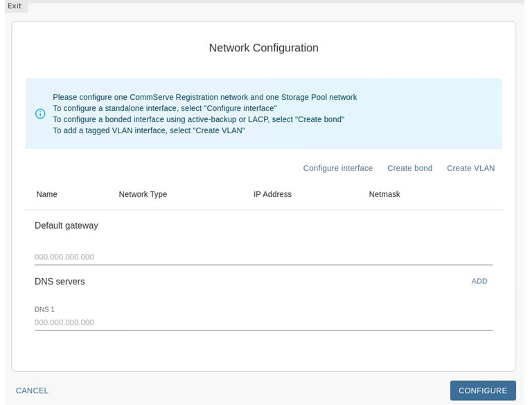
Launch the network configuration interface using the following command:
# hsxsetupThe Network Configuration page appears.
-
Create a data protection interface bond as follows:
-
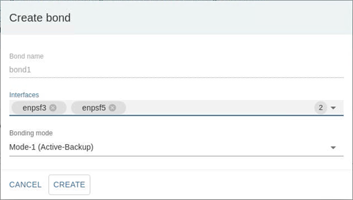
Click Create bond.
The Create bond dialog box appears.
-
From the Interfaces list, select the data protection interfaces. (enpsf3 or enpsf5)
-
From Bonding mode list, select either active-backup (Mode 1) or LACP (Mode 4).
Note
The same bonding mode must be used for both the data protection and storage pool interfaces.
-
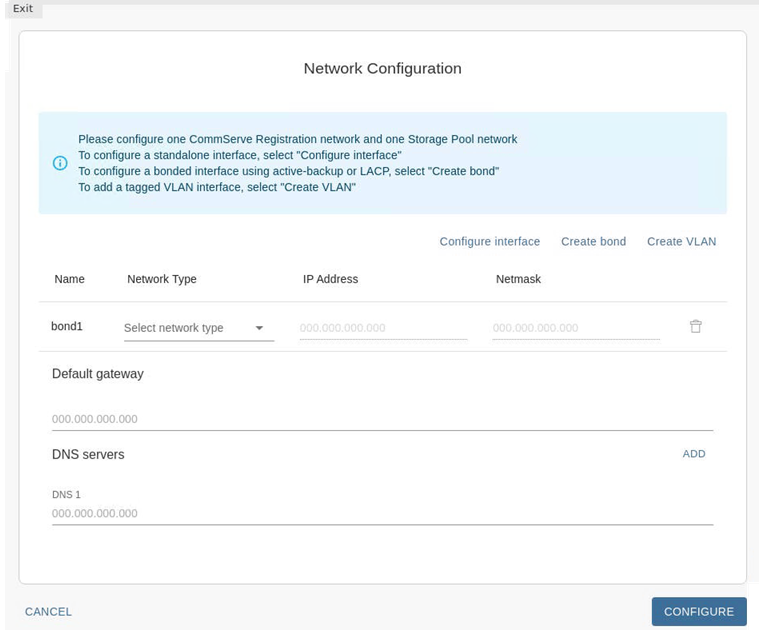
Click CREATE.
The bond1 interface appears in the Network Configuration page.
-
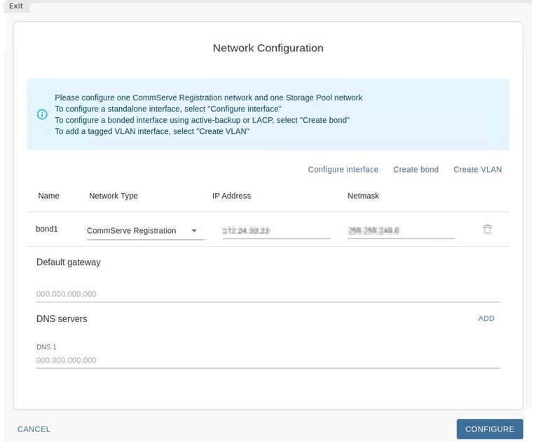
From the Network Type list, select CommServe Registration
-
Add the IP Address and Netmask in the respective boxes.
Once completed your screen should be similar to the one shown in the following image:
-
-
Configure the storage pool interface (bonded) as follows:
-
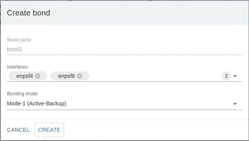
Click Create bond.
The Create bond dialog box appears.
-
From the Interfaces list, select the 2 interfaces that will form the storage pool bond. (For example, enpsf4 and enpsf6 .)
Tip
Hover the cursor over the interfaces to display the speed and MAC address of the physical interface.
-
From Bonding mode list, select either active-backup (Mode 1) or LACP (Mode 4).
Note
The same bonding mode must be used for both the data protection and storage pool interfaces.
-
Click CREATE.
The bond2 interface appears in the Network Configuration page.
-
From the Network Type list, select Storage Pool. This interface will be used exclusively for communication and replication between the HyperScale nodes.
-
Add the IP Address and Netmask in the respective boxes.
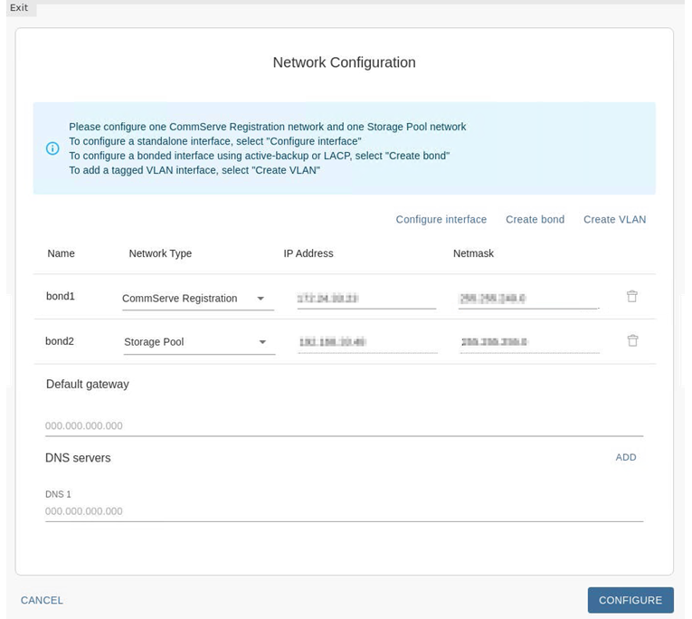
Once completed your screen should be similar to the one shown in the following image:
-
-
Configure the DNS server(s) as follows:
-
In the Default Gateway box, add the IP address associated with the default gateway.
-
In the DNS Servers box, add the IP address associated with the DNS Server.
Click the ADD button to add additional DNS servers. A maximum of 3 DNS servers can be added.
Note
Multiple DNS servers are recommended.
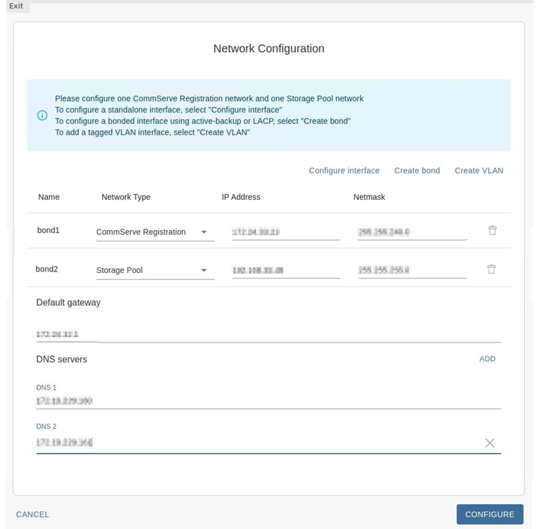
Once completed your screen should be similar to the one shown in the following image: (The number of DNS servers may vary depending on the number of servers available in your environment.)
Note
Verify that the bonding mode is the same for both the data protection and storage pool bonds. Hover the cursor over the check box associated with the bond to view the bonding mode and other information associated with the interfaces.
-
Click CONFIGURE.
The software validates the network. (This may take a few minutes to complete.)
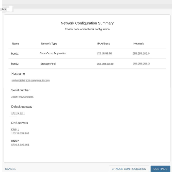
The Network Configuration Summary page appears.
-
-
Verify the network configuration and then click CONTINUE. Verify the following information.
-
IP address and netmask for the data protection interface is accurate.
-
IP address and netmask for the storage pool interface is accurate.
-
Hostname and serial number associated with the node is accurate.
Note
If you need to change the Hostname do so now. To change the hostname modify and correct the DNS records, (forward and reverse records) as discussed in Setting Up the DNS.
-
Default gateway and DNS servers are accurately configured.
Note
If an error is found, or if the hostname was changed, click CHANGE CONFIGURATION to go back and correct the values.
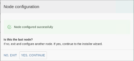
The Node Configuration dialog box appears.
-
-
-
Add the following information:
-
In the Root password and Confirm root password boxes, type a secure password for the nodes.
Tip
Hover the cursor over the Root password box to view the password requirements.
-
In the Password for Restricted shell user - cvbackupadmin and Confirm cvbckupadmin password boxes, type a secure password for the cvbackupadmin user.
-
Click NEXT.
Note
The setup process configures the network for the nodes. This will take some time to complete.
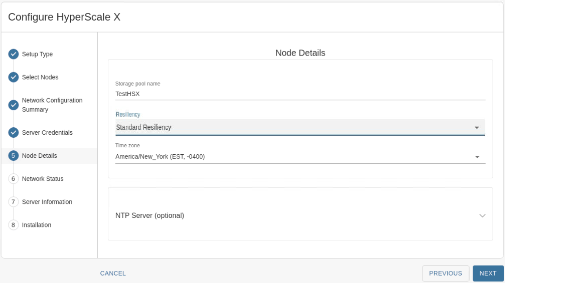
The Node Details page appears.
-
-
Add the following information:
-
In the Storage pool name box, type a name for the storage pool associated with the cluster.
The storage pool name can include numbers and alphabets. Special characters cannot be used in the storage pool name.
Tip
Note down the storage pool name. This will be helpful to identify the storage pool in the Command Center.
-
From the Resiliency list, select the resiliency applicable to the storage pool that you are creating.
-
From the Time zone list, select the time zone in which the nodes are located.
-
In the NTP server box, type a name for the storage pool associated with the cluster.
-
Click NEXT.
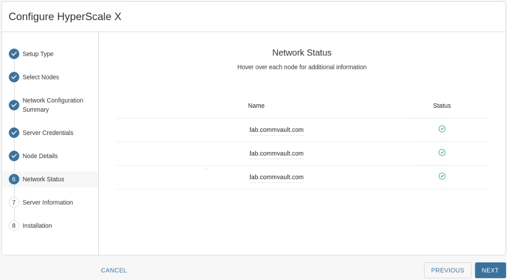
The Network Status page appears.
-
-
Check the status to ensure that all the nodes have a green status to indicate that the network settings is validated and accurate.
Note
If an error is found, hover your cursor over the status icon to view more information on the error. If a node is missing, exit the installer and confirm that all the nodes can ping each other on the storage pool network.
-
Click NEXT.
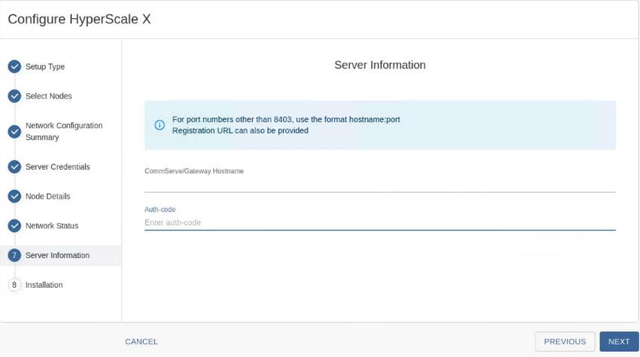
The Server Information page appears
-
Add the following information:
-
In the CommServeGateway Hostname box, enter the fully qualified domain name (FQDN) of the CommServe server based on the endpoint type used in your deployment.
Endpoint Type Example Applicable to SaaS Deployment CommServe FQDN Registration test.commvault.comNo Backup Gateway (default port) test.eastus2.cloudapp.azure.comYes Backup Gateway (non-default port) test.eastus2.cloudapp.azure.com:443Yes Registration URL (Metrics) https://metrics.metallic.ioYes Registration URL (CommServe) https://test.commvault.comNo Note
TCP Ports 8400 & 443 must be open from the nodes to the CommServe server for the registration to work.
-
In the Auth-code box, enter the authorization code to connect to the CommServe server.
-
Click NEXT.
The software validates the information and will start the installation process. This process may take some time (approximately 45 minutes) to complete. You can monitor the progress using the progress bar.
Caution
Do not reboot or stop the installation during this process.
Once the installation is completed, the Installation page appears.
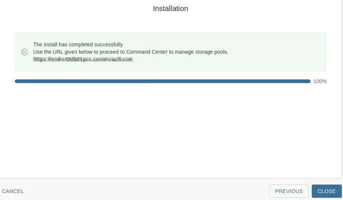
If the storage pool creation fails during the installation, you can manually create the storage pool from the Command Center. For more information, see Creating a HyperScale Storage Pool.
-
-
Click CLOSE.
What to Do Next
Complete the additional configurations that may be required to customize your environment. For more information, see What To Do Next.