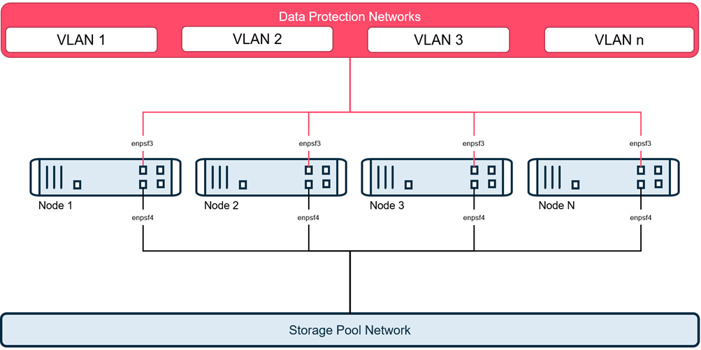
This topology allows multiple tagged VLANs to connect to the appliance using the data protection interface. This allows connection to multiple non-routable networks used to avoid sending backup traffic through a router or firewall.
In this topology, each node requires the following connections:
-
1 - 10 GbE port for data protection which will connect to multiple tagged VLANs to transfer data to and from the clients being protected and connect to the CommServe server. This will include connections to:
-
2 or more VLAN IDs
-
2 or more IP addresses based on the number of VLANs
One of the vLANs must remain routable to connect to the CommServe server.
-
-
1 - 10 GbE port for storage pool which is a dedicated private network, used for communication and replication between the HyperScale nodes.
VLAN interfaces cannot be configured on the storage pool interface.
Note
VLAN topology connects multiple VLANs directly to the HyperScale X Reference Architecture nodes over a single physical connection. This is typically used to connect directly to different networks to avoid traversing routers or firewalls that can become a bottleneck, or to connect to isolated networks. This setup does not provide network redundancy and hence should be combined with the bonded VLAN configurations.
Network Requirements
In this topology, the number of IP addresses required depends on the number of VLANs. For example, if you have 3 VLANs, 10, 20 and 30, you will require 3 IP addresses per node, as follows:
-
1 - 10 GbE data protection port connected to the VLAN IP addresses for each of the VLANs used for data protection.
Out of the available VLANs, one network should be routable and the other network(s) can be non-routable. The routable network will be used for CommServe server registration, in addition to data protection operations. All non-routable VLANs will be used exclusively for data protection operations.
-
1 - 10 GbE port for the storage pool which is a dedicated private network, used for communication and replication between the HyperScale nodes. This requires a corresponding IP address for the storage pool network.
Note
Data Protection and storage pool networks MUST be on two separate subnets.
The following network names and IP addresses are required for this topology:
|
Node 1 |
Node 2 |
Node 3 |
Node n |
|
|---|---|---|---|---|
|
Data Protection Fully Qualified Domain Name* |
|
|
|
|
|
Data Protection vLAN Address* |
|
|
|
|
|
Data Protection Netmask* |
|
|
|
|
|
Data Protection Gateway* |
|
|
|
|
|
Data Protection DNS 1* |
|
|
|
|
|
Data Protection DNS 2 |
|
|
|
|
|
Data Protection DNS 3 |
|
|
|
|
|
Storage Pool IP Address* |
|
|
|
|
|
Storage Pool Netmask* |
|
|
|
|
|
Data Protection NIC Port 1 Card 1 MAC Address |
|
|
|
|
|
Data Protection NIC Port 1 Card 2 MAC Address |
|
|
|
|
|
Storage Pool NIC Port 2 Card 1 MAC Address |
|
|
|
|
|
Storage Pool NIC Port 2 Card 2 MAC Address |
|
|
|
|

* Required fields Each node should be resolvable to the CommServe server. The following information is required for the vLANs. (The following section is provided with examples for illustrative purposes. Replace them with the appropriate IP addresses in your environment.)
|
vLAN1 |
|
|
|
|
|---|---|---|---|---|
|
vLAN1 Description |
Infrastructure |
|
|
|
|
vLAN1 ID |
10 |
|
|
|
|
vLAN1 Address |
172.16.10.101 |
172.16.10.102 |
172.16.10.103 |
|
|
vLAN1 Netmask |
255.255.255.0 |
|||
|
vLAN2 |
|
|
|
|
|
vLAN2 Description |
Marketing |
|
|
|
|
vLAN2 ID |
20 |
|
|
|
|
vLAN2 Address |
172.16.20.101 |
172.16.20.102 |
172.16.20.103 |
|
|
vLAN2 Netmask |
255.255.255.0 |
|||
|
vLAN3 |
|
|
|
|
|
vLAN3 Description |
Sales |
|
|
|
|
vLAN3 ID |
30 |
|
|
|
|
vLAN3 Address |
172.16.30.101 |
172.16.30.102 |
172.16.30.103 |
|
|
vLAN3 Netmask |
255.255.255.0 |
Note
If you have more than 3 nodes expand the columns in this table to include all the nodes that you plan to setup.
Similarly. depending on the number of vLANs in your environment, add rows to include the information for all the vLANs.
CommServe Requirements
You will require the following information to connect to an existing CommServe server:
|
CommServe hostname (FQDN) |
Fully qualified hostname (FQDN) associated with the existing CommServe server. Note TCP Ports 8400 & 443 must be open from the nodes to the CommServe server. |
|
Username |
Username associated with the admin user. |
|
Password |
Password for the admin user. |